Track and trace by laser marking
Making a mark in the press shop - with evoTrQ to the transparent blank
A evoTrQsystem is currently commissioned by an OEM, evoTrQ in its plants worldwide and another international player in the automotive industry has just has just ordered a system ordered. We have therefore developed evoTrQ
already a total of 10 laser stations for the cutting system and 15 FOL camera systems for the most various pressn were delivered.
The system proves its worth, as with evoTrQ relies on the laser marking of the individual circuit boards is used. The advantage of this laser marking is, that you can follow the material throughout the but the labeling after painting however no longer visible . If necessary, however, the paint could be removed again, thus making the lettering visible again. This is extremely useful in the event of an accident, as by reading in the 11-digit inscription code one can can clearly see which manufacturer supplied the material and what the material properties of the material used were, for example. Structural parts can from the outset also markedt bethat the lettering can still be read after painting.
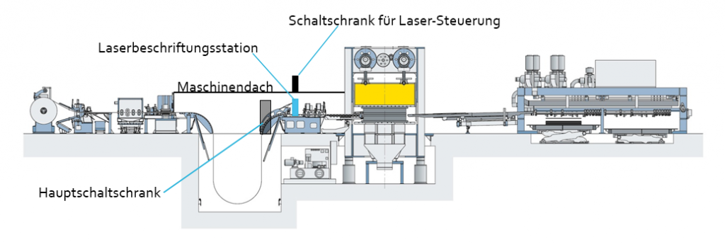
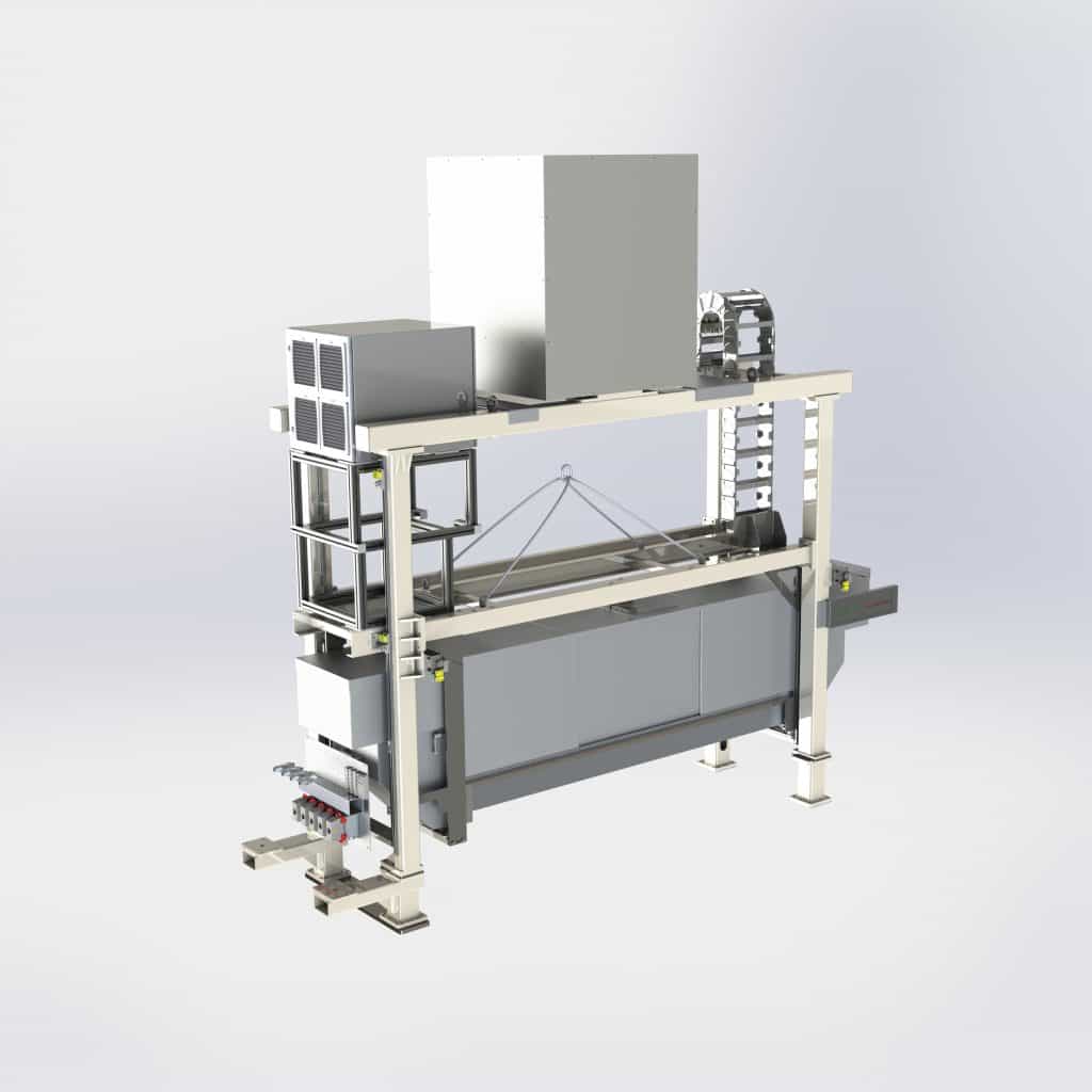
In principle, laser marking is carried out in the coil line in a continuous process. It doesn’t matter how muche Parts can be cut consecutively or in parallel. The laser system ist can be configured accordingly.
After labeling, the current data of the material is assigned to the platinum number in the cloud. These include oil film thickness, roughness, tensile strength and other technical data. For example, it is possible to determine whether the blank was cut at the beginning, in the middle or at the end of the coil. Especially at the beginning and end of the belt, the material thickness and other values may vary.
In the meantime, there are also efforts to have the strip of the delivered coil printed with a code to which corresponding material parameters are assigned in relation to the length – such as the strip thickness, for example. This code is read with a camera in the coil line and the measured values behind the code are assigned to the boards. This also allows you to track changes in values over time and incorporate them into the process.
The resulting stacks of blanks are destacked at the press line and a camera system reads FOL the lasered code to assign further data from the press to the material. In this way, it is possible to analyse the properties of the individual parts at any time, from the cut blank to the finished car.
Press contact
-
Im Gewerbepark A52
D-93059 Regensburg - info[at]evopro-ag.de
- (+49) 941 899645-0
- (+49) 941 899 645-99